Grounding in a private home is a problem that needs to be solved first. Grounding solves the problem of protecting consumers from the damaging effects of electric current. If the insulation of wires and devices is faulty, current flows through grounding.
In this case, the protection device (RCD) is triggered and the voltage is cut off.
Grounding works fully if installed correctly and in compliance with all norms, rules and requirements of regulatory documents. When performing installation yourself, you should remember this and strictly follow these requirements.
Another function of grounding is the proper operation of electrical appliances. Some of them require a direct connection to ground, even if it is in the outlet. That’s why appliances have a special bolt (electric oven, washing machine, microwave).
When touching household appliances with wet hands, you often feel a slight tingling sensation. It is not dangerous, and you can get rid of it by connecting the ground directly to the case.
Do you need a grounding device when building your house?
The essence of grounding is that it is a device that directs electric current when electrical devices malfunction and are shorted to the housing along the path of least resistance to the ground.
Ground bus connection for entry into the house
Therefore, all current is directed to the ground loop and does not pose a danger when a person touches dangerous devices or wires.
The mandatory use of grounding for any private residential building is determined by the rules and regulations (PUE, GOSTs, SNIP).
Another purpose of the grounding system: increases the durability and reliability of household appliances. It protects against network interference, overvoltage and sources of electromagnetic radiation.
Reasons why electric shock occurs
In most cases, the cause of electrical injury is a phase short circuit to the metal body of the device. This occurs due to the deterioration of the insulation on the wires due to aging or overheating. A person who touches the body becomes energized and receives an electric shock.
Appliances that work with water are especially dangerous: boilers, washing machines, dishwashers, etc. Moisture conducts electricity well.
If it comes into contact with a current-carrying element, for example, the spiral of a heating element when its tube is depressurized, then not only the housing, but also the communications along with the water flowing through them come under voltage.
Grounding systems. Which one is better to use?
There are six such systems, but in our reality, as a rule, two are used: TN-SC and TT. Consider TN-SC, this circuit provides that the neutral wire (N) at the substation is grounded. In this case, earth (PE) and zero (N) are supplied to a private household by one wire (PEN) and then at the consumer’s electrical panel they are divided again into two.
TN-SC grounding schemes for a private house
In the case of using such a grounding scheme, the presence of automatic circuit breakers is sufficient for protection; an RCD is not necessary. But, you should know that when the PEN wire to the household breaks, a phase voltage appears on the ground bus in the house. According to the PUE rules, PEN wire protection and grounding on poles are required after 100 or 200 meters.
Due to long-term use and wear and tear, most power lines do not meet these requirements. Therefore, it is recommended to use the TT system. In this scheme, the PE wire goes to the panel from the ground loop, and not from the substation (TN-SC scheme). In this system, the protective wire is more protected, but it is necessary to use an RCD or a circuit breaker. Without them, protection is not provided; their use is mandatory.
TT grounding diagram for a private house
PUE 7, clause 1.7.59 states that if the electrical safety conditions in the TN system cannot be ensured (i.e. the main line is in such a deplorable state that it cannot ensure the reliability of the PEN conductor), then only then is it allowed to be grounded according to the scheme TT.
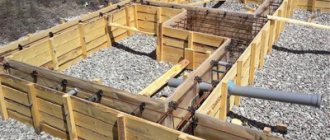
What is a ground loop: definition and device
A ground loop is an electrical device with low electrical resistance that allows you to quickly drain electric current into the ground. It consists of two parts connected to each other - an external and internal system. The connection of these parts is carried out in the electrical panel located at the entrance to the house.
The external system is a device that allows electric current to pass into the ground and then distribute it over an area. It usually consists of several electrodes driven (buried) into the ground and connected by welding with plates of a certain cross-section. From them, the welded tire extends into the shield, where it is connected to the inner part.
Grounding installation in a private house
What is an internal subsystem? This is the distribution of grounding wiring throughout all rooms and areas of the house to sockets and to powerful electrical installations. A common bus is formed, which is connected to the external circuit in the electrical panel.
The protective properties of grounding are very simple. If the insulation of the wires is broken, the current from the electrical network through the wires of the internal system enters the external ground loop. It flows into the ground along the electrodes of this circuit. It is known from electrical engineering that the earth has a large electrical capacity, which gives confidence in the absorption of such electrical leaks.
How to calculate the parameters of the main grounding elements
Based on the results of such calculations, a drawing of the grounding device of the facility is designed.
Important! The device, mounted in accordance with all the calculated data of the grounding scheme, allows you to achieve maximum operational efficiency of the entire protective grounding complex.
The basis of the calculations is the permissible limits of step and touch voltage. Based on them, the configuration (size, number) of grounding conductors and the principle of their placement are calculated.
Calculations are performed based on the following data:
- Description of the characteristics of specific electrical equipment: installation type; main structural elements of the device; operating voltage; Possible options that allow grounding of neutrals of both transforming and generating devices.
- Grounding configuration. Such data is necessary to determine the optimal immersion depth of the electrodes.
- Information about studies conducted to measure soil resistivity in a specific area. Additionally, the climatic information of the zone in which the system is being installed is taken into account.
- Information on suitable natural earthing elements that can be used in your work. Data are needed on the real values of current spreading in these objects. They can be obtained by special measurements.
- The result of a standard calculation of the exact indicators of the estimated current short circuit on the soil.
- Calculated values of regulatory standardization of permissible voltage characteristics according to PUE.
- Indicators of resistance to seasonal freezing of the soil layer during the period of drying and freezing. Taking into account such values is necessary for calculating grounding elements that are located in a homogeneous environment. Special standardized coefficients are applied.
- If it is necessary to install a complex group of grounding conductors, consisting of several elements, it is necessary to know all the potentials that will be induced on the mounted electrodes. To do this, we need data on the resistance values of all soil layers.
Important! If the system is placed in two layers of soil, the resistance value of each of them is taken into account. This is necessary to determine accurate data on the power parameters of the top soil layer.
Types of ground loops
For the grounding system to operate effectively, it must distribute the current “draining” into the ground over several electrodes that increase the dissipation area. There are two main types of grounding systems.
Ground loop - triangle
This type of circuit uses three pins, which are welded using strips into a triangle with equal sides. The length between the electrodes is selected depending on the length of the electrode penetration to two such depths. Those. for an electrode length (depth) of 2m, the side of the triangle will be 2-4m.
Ground loop - triangle
Linear
If it is impossible to make a closed figure due to the configuration of the area, a variant of several electrodes is made, they are placed in a semicircle or in a line. The gap between the driven pins should be 1-1.5 times the immersion depth of the pins. The disadvantage of this method is the large number of electrodes.
Ground loop - linear
The proposed types are the most used in the design and installation of grounding systems. It can be made in the form of any geometric figure (rectangle, circle, etc.), but you must understand that this will require an appropriate number of grounding pins. The main advantage of such systems is that if the connection between the electrodes is broken, the functions of the grounding system are preserved.
Important!
The linear circuit operates on the principle of a garland and damage to the jumper puts a certain section of it out of service.
Bottom line
To summarize all that has been said, let’s pay attention to the recommendations shared by experienced craftsmen:
- Before starting installation work, it is advisable to prepare a drawing of the future structure, which may be needed during further operation. If it is available, it is easier to recall the layout of the pins in memory.
- Electrode segments can be driven in not only at the corner points of the triangle. They can be placed either in a line or in an arc. The main thing is that the total resistance to current flow created by the entire chain does not exceed 3-4 ohms.
- If it is greater than the normalized value, then the system will have to be modified by adding a couple more rods to it.
- If you have no experience in checking ground resistance yourself, it is best to invite a specialist.
After familiarizing yourself with all the intricacies of the process of assembling and testing the ZK, anyone can try to make it with their own hands.
Ground loop requirements
For effective operation of grounding according to the PUE, it must comply with the rules:
- Grounding pins welded into a circuit must be located at least 1 meter and no more than 10 meters from the house. The most correct distance from the foundation is 2-4 meters.
- The rods must be driven to a depth of 2-3 meters.
- The electrodes are connected using a metal strip using welding. A bus of more than 16 square millimeters is used from the shield to the ground loop. To connect wires to grounding in the shield, it can be done using bolts.
- The grounding resistance for a voltage of 380 volts should be no higher than 4 ohms, and for a voltage of 220 volts - 8 ohms.
The external part of the grounding system is buried in the ground, so certain requirements are imposed on it. It must be below the freezing point of the soil, otherwise the electrodes will be pushed out due to swelling of the earth. The electrodes must be such that they can be driven into solid ground.
Recommended types and parameters of driven electrodes:
- corner metal thickness of at least 4 mm, any size;
- a pipe with a diameter convenient for driving, with a wall thickness of at least 3 mm;
- a rod with a diameter of at least 14 mm, a smaller one bends when immersed in the ground;
- strip for connecting electrodes, at least 3 mm thick and more than 10 mm wide.
The minimum length of the electrodes is chosen to be 1.5 meters, the pins are located at a distance of 1-2 lengths of the electrode. It should be taken into account that the electrodes (their length) should be 15-20 centimeters below the soil freezing level.
Grounding switches
1.7.109. The following can be used as natural grounding electrodes:
1) metal and reinforced concrete structures of buildings and structures that are in contact with the ground, including reinforced concrete foundations of buildings and structures that have protective waterproofing coatings in non-aggressive, slightly aggressive and moderately aggressive environments;
2) metal water pipes laid in the ground;
3) casing pipes of boreholes;
4) metal sheet piles of hydraulic structures, water conduits, embedded parts of valves, etc.;
5) rail tracks of main non-electrified roads and railways and access roads in the presence of a deliberate arrangement of jumpers between the rails;
6) other metal structures of structures located in the ground;
7) metal shells of armored cables laid in the ground. Cable sheaths can serve as the only grounding conductors when there are at least two cables. Aluminum cable sheaths are not allowed to be used as grounding conductors.
1.7.110. It is not allowed to use pipelines of flammable liquids, flammable or explosive gases and mixtures, and sewerage and central heating pipelines as grounding conductors. The specified restrictions do not exclude the need to connect such pipelines to a grounding device for the purpose of equalizing potentials in accordance with 1.7.82.
Reinforced concrete structures of buildings and structures with prestressed reinforcement should not be used as grounding conductors, however, this restriction does not apply to overhead line supports and outdoor switchgear support structures.
The possibility of using natural grounding conductors based on the density of currents flowing through them, the need for welding reinforcing bars of reinforced concrete foundations and structures, welding anchor bolts of steel columns to reinforcing bars of reinforced concrete foundations, as well as the possibility of using foundations in highly aggressive environments must be determined by calculation.
1.7.111. Artificial grounding conductors can be made of black or galvanized steel or copper.
Artificial grounding conductors should not be painted.
The material and smallest dimensions of grounding conductors must correspond to those given in Table 1.7.4.
1.7.112. The cross-section of horizontal grounding conductors for electrical installations with voltages above 1 kV should be selected according to the condition of thermal resistance at a permissible heating temperature of 400 °C (short-term heating corresponding to the duration of the protection and tripping of the circuit breaker).
If there is a risk of corrosion of grounding devices, one of the following measures should be taken:
increase the cross-sections of grounding conductors and grounding conductors, taking into account their estimated service life;
use galvanized or copper grounding conductors and grounding conductors.
In this case, one should take into account the possible increase in the resistance of grounding devices due to corrosion.
Trenches for horizontal grounding conductors must be filled with homogeneous soil that does not contain crushed stone and construction waste.
Grounding electrodes should not be located (used) in places where the ground is dried out by the heat of pipelines, etc.
Developing a grounding scheme
In order to organize a grounding device for a private house, it is necessary to work out a grounding circuit diagram. The most popular and most frequently used is the triangle diagram.
As a rule, 3 electrodes stand at its vertices; you can add additional ones, which are driven in a straight line between the vertices.
If it is impossible to make such a contour, the electrodes can be installed in a line, rectangle, semicircle or wave. But it should be noted that the triangular ground loop scheme is much more efficient.
Video
Coffee capsule Nescafe Dolce Gusto Cappuccino, 3 packs of 16 capsules
1305 ₽ More details
Coffee capsules Nescafe Dolce Gusto Cappuccino, 8 servings (16 capsules)
435 ₽ More details
Batteries
Ground loop materials
The electrodes for the grounding system are made from a durable metal profile or rod. If they are thick enough, their electrical resistance must satisfy the requirements. They can be driven into the ground relatively easily by hammering them. Materials used for the manufacture of the ground loop:
- Kernel. A rod with a diameter of more than 14 mm is taken. Reinforcement, as a rule, is not used for these purposes, because When hardening reinforcement, its resistivity increases.
- Pipe. Diameter more than 40 mm, wall thickness not less than 4 mm. It is recommended to make holes at the bottom of the pipe. In arid climates and weather, salt water can be poured into the pipe, this increases the electrical conductivity of the soil.
- Corner. Size 50x50, thickness at least 4 mm. The bottom of the corner is made sharp, which facilitates the process of driving it into the ground.
Clutchless rods
By the way, despite all the advantages and good contact, many consider threaded connections to be the weakest point of such modular systems.
Think about water pipes lying in the ground. After several years of operation, it is the threaded couplings that rust first.
The same thing can happen with pins. In addition, at the moment of hammering with a vibrating hammer, the connection often weakens. Simply put, the thread is unscrewed.
Experienced installers, after each entry of another rod into the ground, tighten the electrode along the thread. At this point another mistake occurs.
When you tighten a smooth pin or socket with a serrated wrench, you scratch and strip the copper layer from the surface. What this leads to was discussed above.
After 3-4 years, instead of a full-fledged electrode, you will be left with a hollow copper tube with rusty dust inside.
This way you will not touch either the electrode or the coupling.
Also note that in all coupling kits, the coupling itself is slightly wider than the diameter of the rod. What does this mean? A narrower electrode, when entering the ground following such a coupling, will not be in close enough contact with the soil surface
To obtain real resistance indicators, sometimes you have to wait several days until the earth crumbles and compacts all the free spaces
A narrower electrode, when entering the ground following such a coupling, will not be in close enough contact with the soil surface. To obtain real resistance indicators, sometimes you have to wait several days until the earth crumbles and compacts all the free spaces.
Therefore, many people prefer a different type of deep grounding rods. For example, like OBO Bettermann with the BP (Bundes Post) system.
In such sets, the pins are joined together without threads, using the pressing method.
This is something like a tongue-and-groove connection with a self-release pin. When driven in, the tenon is tightly wedged into the groove and an absolutely monolithic connection is obtained.
Sometimes inside the hole at the end of one rod there may be a lead ball, which, when struck, fills the entire space even more tightly.
Therefore, if you do not trust couplings and want to eliminate the human factor, buy such kits.
What to make metal connection from
Metal connection, i.e. The connection of electrodes driven into the ground is carried out using the following materials:
- Copper wire or bus, cross-sectional area - 10 square meters. mm and more.
- Steel tire, cross-section - 48 sq. mm.
- Aluminum wire or strip, cross-sectional area more than 16 square meters. mm.
For such purposes, a steel strip of 25-30x5 mm is preferable. The connection of such a strip to the electrodes is made using electric welding, which ensures a reliable connection. When using aluminum or copper conductors, the connection is made using a bolted connection.
Location of grounding device pins
How to connect the electrodes
In order for grounding to quickly remove current, the electrodes must be connected to each other using metal with low resistance. For this purpose, either steel or non-ferrous metals - aluminum or copper - are used. In this case, it is necessary to correctly calculate the cross-section of the connecting bus, which will ensure the efficiency of the entire system.
Minimum cross-section, depending on material:
- The copper busbar or wire must have a cross-section of at least 10 mm2.
- The aluminum connector cannot be thinner than 16 mm2.
- Steel strip with a cross-section of at least 48 mm2.
It is important to remember that non-ferrous metals, unlike steel, cannot be welded to ordinary iron, and therefore, if copper or aluminum is used as a busbar, threads are cut on the electrodes to secure the strip to the bolts.
Self-installation of grounding
A location must be selected for the ground loop. It should be located where people and your pets will least likely enter. There should be a distance of more than 1 meter from the foundation. Marks are made on the site where the pins will be located. They are arranged in the shape of an equilateral triangle.
Excavation. After applying the markings in a straight line between the pins, a trench half a meter deep is dug. The same trench for laying the busbar is dug from the ground loop to the input electrical panel.
Next, adhering to the chosen pattern, we drive in the rods to the required length. They are connected by a strip of metal by welding. Next, the busbar welded to the ground loop is laid in the trench to the electrical panel.
Entering the house. The bus connected to the house is inserted into the electrical panel. A hole is drilled in it and connected with a bolt and nut to a specific cable core. With the TN-CS scheme, the busbar inserted into the shield is connected to the busbar - the splitter.
Checking the finished grounding
After completing all installation and connection operations of the ground loop, it is necessary to check it by measuring its electrical resistance. The parameters of this value should not exceed the limits specified in the regulatory documents.
You can use a simple test method at home. A light bulb from 100 to 150 W is connected between phase and ground.
Checking grounding performance using a lamp
Based on the glow of the lamp, conclusions are drawn:
- if the lamp does not light up, the grounding is done incorrectly;
- the lamp burning with a dim, dim light indicates a poor-quality connection of the ground loop elements or connections during connection;
- A bright lamp indicates good grounding performance.
During such a check, if there is an RCD in the circuit, it may operate, which indicates the operating condition of the circuit.
Check with a multimeter.
Checking grounding with a multimeter
It is carried out according to the following method:
- it is necessary to apply voltage by turning on the input circuit breaker;
- On the multimeter, select the voltage measurement mode;
- We connect the ends of the multimeter between the phase and neutral wires. The device should show a value around 220 volts;
- We make a similar measurement between the phase and the ground wire. The voltage may be slightly different from the previous measurement, but its very presence indicates the presence of ground;
- if there is no voltage, then there is no grounding, or it is not working.
The inspection can be entrusted to professionals. This check is shown in the video:
Checking the ground loop by professionals
Compliance with safety regulations
Before carrying out any work on the grounding device, you must do one of two things:
- cut off power to the house;
- disconnect the ground wire from the main bus.
Grounded parts of electrical installations may become live at any time, incl. and during manipulations with the contour. If it is not turned off, the user will receive an electric shock.
Before performing work on the electrical panel, the house must also be de-energized. After turning off the machine, make sure there is no voltage using the phase indicator (indicator screwdriver).
Ready-made kits for grounding installation
Making grounding yourself can significantly reduce costs. But there are ready-made kits that can increase the reliability of the circuit.
Ready-made kit for grounding installation
The following models are available on the market:
Elmast - the system is manufactured in Russia. Cost - 8000 rubles.
ZandZ - stainless steel electrodes. The depth of immersion in the ground is up to 10 meters. The kit will cost 23,500 (electrodes 5 meters long).
Galmar - average cost - 41,000 rubles (electrodes up to 30 m long).
There are several models on the market for Russian consumers. This gives you a lot of options to choose from. The cost ranges from 6,000 to 28,000 rubles.
Installation of a ground loop in a private house